A Guide To VRLA Battery Discharge Testing.
This article discusses test discharging of VRLA batteries. The principal is almost identical to the procedure that should be followed when testing vented Lead-Acid batteries but some important changes are necessary to obtain the correct results.
The article covers the broad spectrum of testing and some manufactures and users may prefer to test batteries in a slightly different way. Never the less, this article follows the UK accepted practice as given in BS 6290 Part 4 1997. It also discusses the International Standard IEC 60896 -
The article does not discuss “fault finding” which can be found in another article.
1) INTRODUCTION
1.1) BS 6290 Part 4 principally considers the 3h to n x 1.80Vpc at 20°C rate as the preferred discharge rate when capacity testing. IEC 60896 suggests 3h to n x 1.70Vpc at 20°C or 25°C. Within the BS additional discharge rates are listed for discharge tests between 1h and 10h. Also listed are 4 discharge rates of 1m, 5m, 15m, and 30m. There is a recommended final voltage for all discharge rates.
1.2) Frequently, the user will want to test at a discharge rate other than those recommended in the BS or IEC and this can normally be accommodated. For example, the 10m is frequently specified for UPS batteries to a final voltage of 1.70Vpc. Any test can be carried out but it is important to agree these before commencement and agree the pass / fail points.
2) COMMISSIONING CHARGE
2.1) Before any test is carried out, the battery must be commission charged in accordance with the manufacturers procedures. For VRLA AGM batteries, this can normally be achieved by applying a voltage to the battery terminals averaging either typically 2.40Vpc for 48 hours or at a voltage of typically 2.27Vpc for 6 days. Other voltages and times may be used but the manufacturer must approve any method. For VRLA GEL product, the voltage may be increased to typically 2.45Vpc for the 48h charge and reduced to typically 2.25Vpc for the 6-day charge.
2.2) AGM 2.40Vpc and 2.45Vpc GEL for 48 Hours Method.
For all commissioning charge procedures, the battery must be located in a well ventilated environment at an average voltage of 2.40Vpc / 2.45Vpc with a minimum current equivalent to 5% of the A·h capacity expressed as C3 A and a maximum current of 10% C3 A·h capacity expressed as A. The battery and battery room must be at a temperature of between +10°C and +35°C. If the battery and room are outside the range 15ºC and 25ºC the charging voltage should be adjusted to compensate. For the correct applied voltage the manufacturer must be consulted.
2.3) AGM 2.27Vpc and 2.25Vpc GEL for 6 Days Method.
Charge the battery in a well-ventilated environment at a voltage recommended by the manufacturer. This voltage is normally the voltage at which the battery will be charged at when in normal service. As with the 2.40Vpc / 2.45Vpc for 48h method, the current available must be not less than 5% of the C3 A. However, the maximum current is often not limited and frequently, 100% C3 A is acceptable. The battery and battery room must be at a temperature of between +15°C and +25°C. If outside this range, the manufacturer must be consulted to establish the correct charging voltage.
2.4) At the end of the 48 hours, 6 days or other approved method, measure and record the typical cell or monoblocs temperature, ambient temperature, charge current total battery voltage and individual unit voltages.
2.5) If any individual unit voltage differs from the average significantly, the battery manufacturer should be consulted before the test carrying out the discharge test. For guidance, the following values may apply as limits.
For 2V cells: maximum difference from the average: 0.10V For 4V units: maximum difference from the average: 0.14V For 6V units: maximum difference from the average: 0.22V For 12V units: maximum difference from the average: 0.44V For 16V units: maximum difference from the average: 0.55V
2.6) No matter which charging method is used, the manufacturer must approve it and a record of the charge must be made.

3) DISCHARGE TEST
3.1) Typically and to comply with the requirements if BS 6290 Part 4, the battery must be held on open circuit for not less than 1h and not more than 24 hours before commencing the discharge test. However, in a real live situation when the mains power fails, the battery will go from float to discharge immediately. Therefore, many users stipulate that the test shall be performed “direct from float”. It is rare that this procedure is a handicap to the battery and in most cases; it is to the batteries advantage.
3.2) Before starting the test, record the surface temperature of several units. This temperature shall be used in the final analysis for the temperature corrected discharge time. This is the only temperature that is used to “temperature compensate” the discharge time. For vented products the temperature is recorded at intervals and the average is used to compensate the discharge time. Also measure and record the ambient temperature near the battery. The unit and ambient temperature must be within ±5ºC. If they are not, do not start the test and contact the Company for advice.
3.2.1 The battery may be discharged at any agreed discharge rate including constant current, constant power or constant resistance. In all cases, the parameter should be maintained within ±5%, for the whole of the discharge.
3.2.2 During the discharge test, measure and record at regular intervals, the parameters below. Typically, at least 10 measurements should be taken at regular intervals.
3.2.3 The individual unit voltages, including one inter unit connector. 3.2.4 The overall battery voltage, at the battery terminals. 3.2.5 The discharge current or power if the discharge is at constant power.
3.3 When the overall battery voltage, when measured at the battery terminals, falls to the minimum accepted, record the time, and all individual unit voltages. Stop the discharge test.
3.4 The battery should be recharged as soon as possible. For high current discharged such as 5-minute constant power, the battery may be elevated above the ambient by several degrees. In spite of this, the battery may be recharged immediately. If the recharge cannot be started immediately, the manufacturer usually accepts a stand period of up to 12 hours. However, this should be confirmed.
3.5 If during the discharge test, the voltage of any individual 2V cell falls to below 0.5V, it is recommended that the test be stopped. Similarly for individual voltage of 6V units falling below 3V, 12V units falling below 6V, and 16V units falling below 8V, stop the test.
4) PASS / FAIL CRITERION
4.1 The test shall be deemed passed providing the discharge time corrected for temperature meets the requirement
4.2 The battery manufacturer should be consulted for the actual temperature correction values for the type of battery and discharge that it has been tested at.
4.3 The British Standard allows for individual cell or monobloc voltages to be below the average but the battery, as a complete system must meet the requirements. For example, BS 6290 Part 4 states that as a complete battery the terminal voltage shall be not less than n x 1.80Vpc at the end of a standard 3h test and all cells shall be not less than 1.75Vpc after 2h 30m. It will be apparent that if an individual cell has marginally exceed the 1.75Vpc at 2h 30m then there is still a likelihood that the battery as a complete system will fail or the individual cell voltage will be lower than the suggested 0.5V (see the last paragraph in section 3.4 above. This principal may be extended to cover different discharge rates. It is suggested that a minimum voltage of 0.05Vpc below the minimum average accepted as a pass at the end of discharge time at 83% of the discharge time. For example, if the discharge test has to run for 10m with a minimum voltage of 1.65Vpc, then every cell shall have a voltage of not less than 1.60Vpc after 8m 20s.
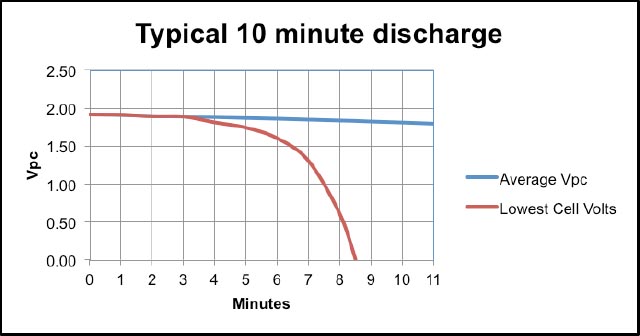
4.4 The graph below illustrates a battery tested at the 10m rate where the total battery voltage exceeded the requirement but one cell collapsed after about 4m. This battery test should be regarded as failed. In these circumstances, the faulty cell should be replaced. Although the customer may insist on a complete battery re-test it is often acceptable to test a single cell separately and insert it into the battery system. This avoids a complete battery re-test. This battery system consisted of 333 single cells of 950Ah each. In a subsequent teardown analysis of the battery the fault was discovered as an internal short caused by a bent end negative plate shorting to an adjacent positive plate
